Body text
Measuring the radiation pattern of the BRAMS transmitter
Since 2010, the BRAMS transmitter located in Dourbes has been emitting a pure continuous sine wave towards the zenith at a frequency of 49.97 MHz. The antenna is made of 2 crossed-dipoles and a ground plane made of an 8m × 8m metallic grid with the aim of emitting a circularly polarized wave in an isotropic way around the zenith.
Due to inadequate adaptation of the two antennas, the radiation pattern was unfortunately very different from the theoretical one and in-situ measurements were necessary to determine the exact amount of power transmitted in a specific direction. Knowing this radiation pattern is essential for many studies using BRAMS data.
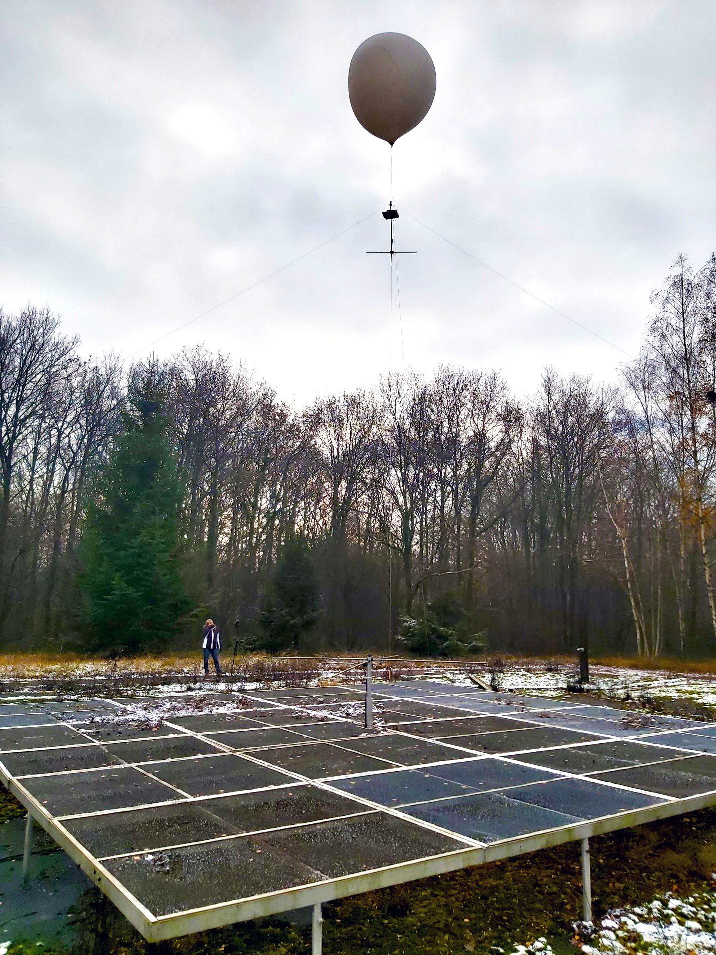
A captive weather balloon with a payload platform
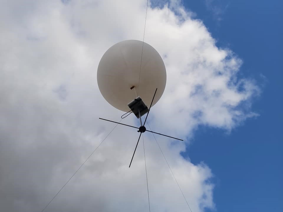
In the course of 2019, a payload was designed to measure in-situ the radiation pattern of the transmitter. It comprises a pair of receivers located on a platform and connected to two short dipole antennas in order to measure both polarized components. The platform was hung below a captive weather balloon filled with helium. Due to the proximity of the platform, the transmitter was only operating at a small fraction of its nominal power.
The platform also hosted:
- an embedded Linux system
- a camera
- a three-axis accelerometer
- a three-axis magnetometer
- a battery
- a GNSS receiver.
Another GNSS receiver remained on the ground, connected to a second embedded Linux system. This provides the necessary position and attitude information with sufficient accuracy.
Discrepancies between the expected and measured radiation patterns
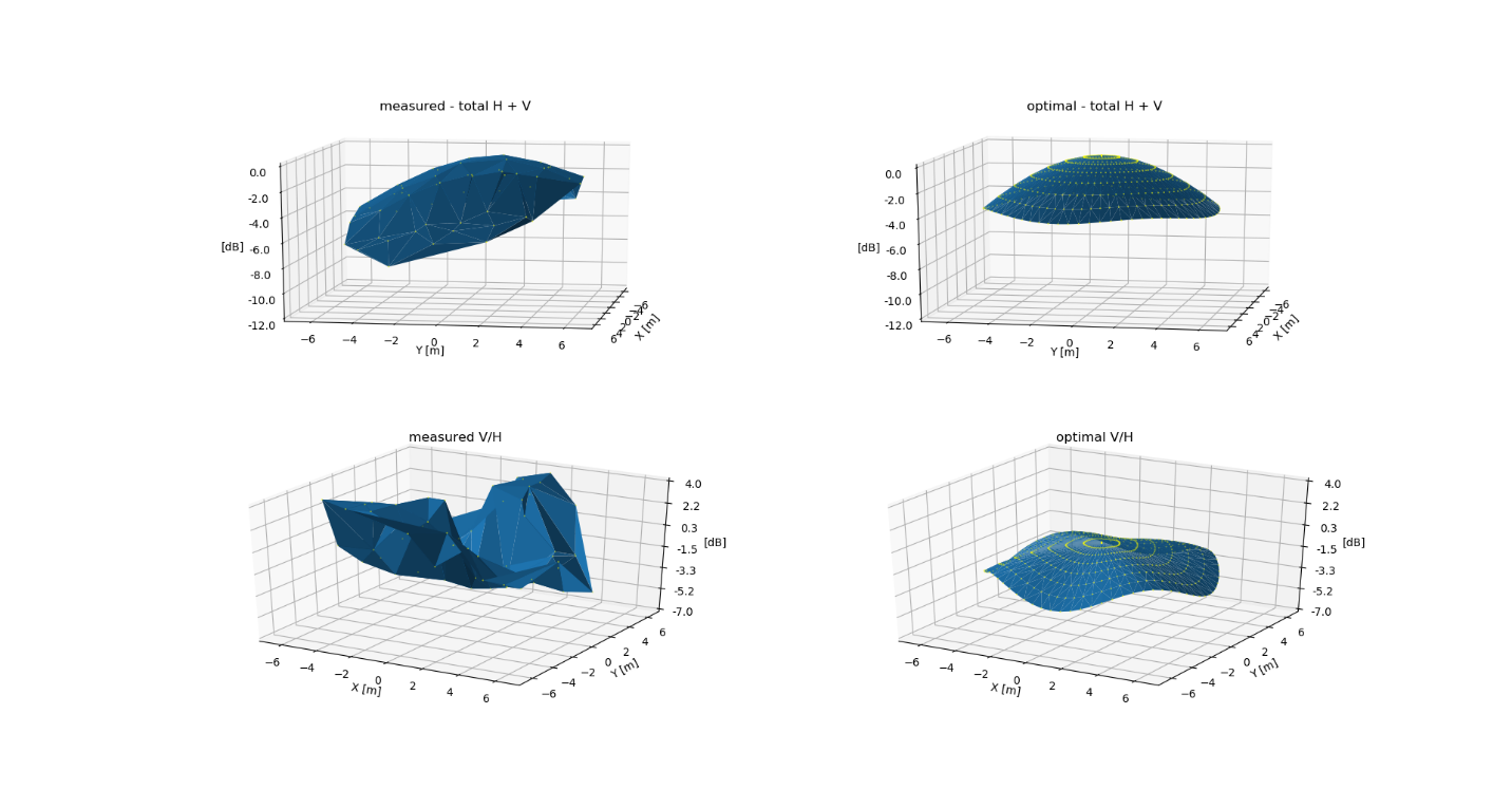
In December 2019, the radiation pattern was sampled in a single horizontal plane, 10 meters above the transmitter. Due to the poor signal-to-noise ratio of the GNSS signals, and hence the lack of accurate GPS positions, images taken by the on-board camera had to be used to determine the platform’s position. The orientation of the platform is calculated using data from the accelerometer, magnetometer and camera images.
The radiation power pattern of the transmitter for elevations greater than 52° was computed and compared to the optimal radiation pattern of the transmitter (assuming ideal match and 90° phase difference at the feed points). The discrepancies between the two patterns are significant, most notably with a maximum pointing 10° westwards and a severe departure from the intended circular polarization. The transmitter was upgraded in June 2020 to correct this behavior.
Further improvements are planned to reduce the dwell time at each position, allowing more measurements, even in light winds.